Deploying a single 42U server cabinet is straightforward; rolling out a 3-rack to 20-rack bayed row requires pre-coordinating pitch alignment, interior side-panel deletion, overhead busway clearances, and continuous equipotential grounding before crates arrive on the loading dock.
Built to EIA-310-E dimensional and static-load engineering standards; structural load test documentation available per project. Return to our parent 42U 800 mm Wide Cable & PDU Racks hub or review 600 mm vs. 800 mm Wide 42U Server Racks.
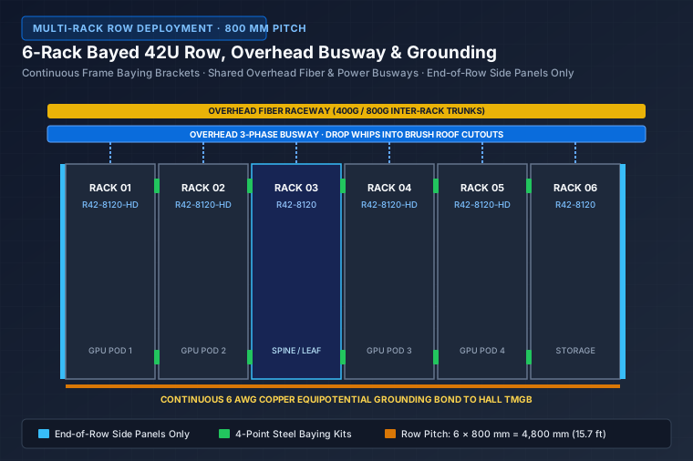
Pre-Delivery Row Specification Checklist
| Row Design Checkpoint | Engineering Standard | Why It Matters on Site |
|---|---|---|
| 1. Row Center-to-Center Pitch | 600 mm (R42-6110) or 800 mm (R42-8120 / R42-8120-HD) | Keeps bayed row synchronized with overhead busway tap boxes and floor tiles |
| 2. End-of-Row Side Panels Only | Order 2 outer side panels per row; delete interior side panels | Eliminates redundant steel between racks, speeds inter-rack patching, cuts freight weight |
| 3. Four-Point Baying Kits | Bolt frames at top-front, top-rear, bottom-front, bottom-rear | Prevents frame gap drift and seals cold-aisle containment air plane |
| 4. Leveling Before Baying | Deploy M16/M12 leveling feet to uniform 2,000 mm laser height | Leveling after bolting twists door frames and binds 3-point swing handles |
| 5. Top Brush Cable Alignment | Match roof brush slots directly under busway tap-offs and fiber drops | Avoids tight cable bends over raw sheet-metal roof edges |
| 6. Continuous Row Grounding | Daisy-chain 6 AWG copper bond from each cabinet M6 stud to hall TMGB | Satisfies TIA-607 equipotential bonding across doors, frames, and overhead trays |
Overhead Power & Fiber Architecture for 6- to 10-Rack Pods
Modern high-density rows separate clean fiber pathways from high-amperage 3-phase power drops right at the cabinet roof:
- Front Zone (Yellow Fiber Raceway): Routes 400G/800G MPO trunks straight down through front corner brush cutouts into the 150 mm side cable fingers of 800 mm racks.
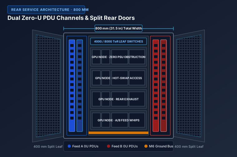
- Rear Zone (Dual A/B 3-Phase Busway Drops): Feeds IEC 60309 or CS8365C power whips directly into rear corner roof cutouts aligned with the left (Feed A) and right (Feed B) Zero-U PDU channels.
- Roof Ladder-Tray Load Capacity: Mount steel waterfall brackets and ladder-tray risers directly onto the structural perimeter rail of R42-8120-HD rather than sheet-metal roof center plates.
Multi-Bay Colocation Row Adjustments
When baying multi-tenant R42-2B or R42-4B colocation cabinets, do not delete interior side panels—keep internally bolted solid steel inter-cabinet partition panels installed between adjacent racks so Tenant A in Rack 01 cannot reach into Tenant B’s bay in Rack 02.
Share your row length, cabinet width, end-of-row side panel count, and overhead drop positions on our 15-Minute Formal Quote page for a row-ready bill of materials and formal quotation.
Standard & Custom-Engineered Models
42U 800×1200 mm Extra-Deep AI GPU Server Rack
800×1200 mm extra-deep 42U AI GPU flagship with 1,500 kg (3,307 lb) static load, >78% hex-mesh airflow, and dual rear Zero-U PDU channels.
Full Datasheet →